Showing posts with label motor. Show all posts
Showing posts with label motor. Show all posts
Friday, July 12, 2013
LMD18200 Motor Controller Schematic
Using the LMD18200 3A H-Bridge designed by National Semiconductors for motion control applications can be designed a very simple motor controller electronic project . Ideal for driving DC and stepper motors; the LMD18200 accommodates peak output currents up to 6A. An innovative circuit which facilitates low-loss sensing of the output current has been implemented.
LMD18200 Motor Controller Schematic

This circuit controls the current through the motor by applying an average voltage equal to zero to the motor terminals for a fixed period of time, whenever the current through the motor exceeds the commanded current. This action causes the motor current to vary slightly about an externally controlled average level. The duration of the Off-period is adjusted by the resistor and capacitor combination of the LM555.
Using this motor driver circuit you can design a 24 DC motor that require a maximum current consumption of 3 amperes .
LMD18200 Motor Controller Schematic
Using this motor driver circuit you can design a 24 DC motor that require a maximum current consumption of 3 amperes .

Thursday, July 4, 2013
DC Servo Motor Circuit Using A3952S
A3952S motor driver is capable of continuous output currents up to 2 A and has an operating voltages range up to 50 V. Warning , the 50 operating voltage is to power the motor , for the logic controller you will need a 5 volts Dc power supply .
DC Servo Motor Circuit Diagram

This simple DC servo motor circuit design that can be used in various electronic projects . As you can see in the circuit schematic this Dc servo motor driver schematic circuit use just one integrated circuit and other few external electronic components .
With bidirectional dc servo motors, the PHASE terminal can be used for mechanical direction control. Similar to when braking the motor dynamically, abrupt changes in the direction of a rotating motor produce a current generated by the back EMF. The current generated will depend on the mode of operation.
DC Servo Motor Circuit Diagram
With bidirectional dc servo motors, the PHASE terminal can be used for mechanical direction control. Similar to when braking the motor dynamically, abrupt changes in the direction of a rotating motor produce a current generated by the back EMF. The current generated will depend on the mode of operation.
Tuesday, May 14, 2013
PWM Motor Speed Control Circuit
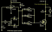 Here is a simple PWM motor speed controller circuit that can be used for varying the speed of low power DC motors .The variation in speed is achieved by varying the duty cycle of the pulse supplied to drive the motor.Of the two gates of IC CD40106B ,N1 is wired as an inverting Schmitt Trigger astable multi vibrator for producing pulses and N2 as an inverting buffer to drive the transistor during positive cycles at base.The duty cycle is set from resistor R2. R1 limits the base current of transistor SL 100.The circuit is ideal for controlling toy motors,hand held mini fans , small blowers etc.
Friday, April 12, 2013
Maximite Stepper Motor Interface
This simple circuit and program listing allows the Maximite microcomputer (SILICON CHIP, March-May 2011) to control a stepper motor. It could be expanded to allow for the control of multiple motors, with four of the Maximite’s external I/O pins used to control each motor with identical driver circuits. A ULN2003 Darlington transistor array (IC1) switches current through the stepper motor’s two windings in either direction. When one of the four Maximite output pins (8, 12, 16 & 20, corresponding to I/Os 19, 17, 15 & 13) goes high, the corresponding output pin on IC1 goes low, sinking current through a motor winding. Conversely, when these pins are high, the corresponding Darlington transistor is off and so no current flows through that portion of the winding.

The centre tap of each motor winding is connected to a current source comprising PNP Darlington transistor Q1 and some resistors. The maximum current is determined by the resistive divider driving its high-impedance base, setting the base voltage to around 9.1V when it is fully on. By adding Q1’s base-emitter voltage (1.4V at 0.5A, as per the data sheet) we can determine that there will be around 1.5V across the 3.3O resistor (12V - 10.5V), resulting in a current of 1.5V ÷ 3.3O = ~450mA. Transistor Q1 must be fitted with a medium-sized flag heatsink (Jaycar HH8504, Altronics H0637) or larger to handle its maximum dissipation of (10.5V - 4.9V) x 450mA = 2.5W.
When one of the Darlington transistors switches off and current flow through the corresponding motor winding ceases, the inductive winding generates a back-EMF current which causes the voltage across that winding to spike. IC1 has internal “free-wheeling” diodes from each output to the COM pin, which is connected to the +12V supply. The back-EMF current flows back into the power supply and the voltage spikes are clamped at about 12.7V, so that the Darlington transistors do not suffer collector reverse breakdown, which might damage them.
A 470µF capacitor provides supply bypassing for the motor while a 47kO pull-up resistor and toggle switch/pushbutton S1 drives input pin 9 of the Maximite, allowing manual control of the motor direction. Table 1 shows the sequence in which the output pins are driven to turn the motor forward; the steps are run backwards for reverse operation. The delay between the steps determines the speed at which the motor rotates. The source code of the sample program is available for download from the SILICON CHIP website (maximite_stepper_motor.bas).

The centre tap of each motor winding is connected to a current source comprising PNP Darlington transistor Q1 and some resistors. The maximum current is determined by the resistive divider driving its high-impedance base, setting the base voltage to around 9.1V when it is fully on. By adding Q1’s base-emitter voltage (1.4V at 0.5A, as per the data sheet) we can determine that there will be around 1.5V across the 3.3O resistor (12V - 10.5V), resulting in a current of 1.5V ÷ 3.3O = ~450mA. Transistor Q1 must be fitted with a medium-sized flag heatsink (Jaycar HH8504, Altronics H0637) or larger to handle its maximum dissipation of (10.5V - 4.9V) x 450mA = 2.5W.
When one of the Darlington transistors switches off and current flow through the corresponding motor winding ceases, the inductive winding generates a back-EMF current which causes the voltage across that winding to spike. IC1 has internal “free-wheeling” diodes from each output to the COM pin, which is connected to the +12V supply. The back-EMF current flows back into the power supply and the voltage spikes are clamped at about 12.7V, so that the Darlington transistors do not suffer collector reverse breakdown, which might damage them.
A 470µF capacitor provides supply bypassing for the motor while a 47kO pull-up resistor and toggle switch/pushbutton S1 drives input pin 9 of the Maximite, allowing manual control of the motor direction. Table 1 shows the sequence in which the output pins are driven to turn the motor forward; the steps are run backwards for reverse operation. The delay between the steps determines the speed at which the motor rotates. The source code of the sample program is available for download from the SILICON CHIP website (maximite_stepper_motor.bas).
Source by : Streampowers
Wednesday, April 3, 2013
DC Motor Speed Controller
This circuit takes advantage of the voltage drop across bridge rectifier diodes to produce a 5-position variable voltage supply to a DC fan or other small DC motor. It is not as efficient as a switch-mode circuit but it has the virtues of simplicity and no switching hash. The four full-wave bridges are connected so that each has two pairs of series diodes in parallel, giving a voltage drop of about 1.4V, depending on the load current.
Circuit diagram:

DC Motor Speed Controller Circuit Diagram
The rotary switch should have "make before break" contacts which should be rated to take currents up to about an amp or so. For higher currents, higher rated bridge rectifiers and a suitably rugged rotary switch (or solenoids) will be required. If you want smaller voltage steps, you could use the commoned AC inputs on the bridge rectifiers to give intermediate steps on the speed switch.
Source by : Streampowers
Monday, March 25, 2013
Fuse Box Ford 1993 F150 Shift Motor Diagram
Fuse Box Ford 1993 F150 Shift Motor Diagram - Here are new post for Fuse Box Ford 1993 F150 Shift Motor Diagram.


Fuse Panel Layout Diagram Parts: electronic clutch feed, transfer case motor control, speed sensor, shift position sensor.
readmore...
Fuse Box Ford 1993 F150 Shift Motor Diagram


Fuse Panel Layout Diagram Parts: electronic clutch feed, transfer case motor control, speed sensor, shift position sensor.
Friday, March 22, 2013
Motor Turn Stall Detector
In single phase AC induction motors, often used in fridges and washing machines, a start winding is used during the starting phase. When the motor has reached a certain speed, this winding is turned off again. The start winding is slightly out of phase to the run winding. The motor will only start turning when the current through this winding is out of phase to that of the run winding. The phase difference is normally provided by placing a capacitor of several µF in series with the start winding. When the motor reaches a minimum speed, a centrifugal switch turns off the start winding.
The circuit diagram doesn’t show a centrifugal switch; instead it has a triac that is turned on during the staring phase. For clarity, the series capacitor isn’t shown in the diagram. Once the motor turns it will continue to do so as long as it isn’t loaded too much. When it has to drive too heavy a load it will almost certainly stall. A large current starts to flow (as the motor no longer generates a back EMF), which is limited only by the resistance of the winding. This causes the motor to overheat after a certain time and causes permanent damage. It is therefore important to find a way to detect when the motor turns, which happens to be surprisingly easy. When the motor is turning and the start winding is not used, the rotation induces a voltage in this winding.
Motor Turn Stall Detector Circuit diagram:

This voltage will be out of phase since the winding is in a different position to the run winding. When the motor stops turning this voltage is no longer affected and will be in phase with the mains voltage. The graph shows some of the relevant waveforms. More information can be found in the application note for the AN2149 made by Motorola, which can be downloaded from their website at www.motorola.com. We think this contains some useful ideas, but keep in mind that the circuit shown is only partially completed. As it stands, it certainly can’t be put straight to use. We should also draw your attention to the fact that mains voltages can be lethal, so take great care when the mains is connected!
Author: Karel Walraven - Copyright: Elektor July-August 2004
Source : http://www.ecircuitslab.com/2011/07/motor-turn-stall-detector.html
Subscribe to:
Posts (Atom)