Tuesday, May 14, 2013
Browse »
home»
circuit
»
control
»
motor
»
pwm
»
speed
»
PWM Motor Speed Control Circuit
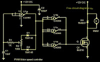 Here is a simple PWM motor speed controller circuit that can be used for varying the speed of low power DC motors .The variation in speed is achieved by varying the duty cycle of the pulse supplied to drive the motor.Of the two gates of IC CD40106B ,N1 is wired as an inverting Schmitt Trigger astable multi vibrator for producing pulses and N2 as an inverting buffer to drive the transistor during positive cycles at base.The duty cycle is set from resistor R2. R1 limits the base current of transistor SL 100.The circuit is ideal for controlling toy motors,hand held mini fans , small blowers etc.

PWM Motor Speed Control Circuit
Here is a simple PWM motor speed controller circuit that can be used for varying the speed of low power DC motors .The variation in speed is achieved by varying the duty cycle of the pulse supplied to drive the motor.Of the two gates of IC CD40106B ,N1 is wired as an inverting Schmitt Trigger astable multi vibrator for producing pulses and N2 as an inverting buffer to drive the transistor during positive cycles at base.The duty cycle is set from resistor R2. R1 limits the base current of transistor SL 100.The circuit is ideal for controlling toy motors,hand held mini fans , small blowers etc.
Subscribe to:
Post Comments (Atom)
No comments:
Post a Comment
Note: Only a member of this blog may post a comment.