Sunday, March 24, 2013
Browse »
home»
diagram
»
4Watt FM Transmitter
TECHNICAL CHARACTERISTICS:
Stabilised tendency of catering: Vcc=12~16V
Frequency of emission: 88~108MHz
Consumption: 100~400mA


4Watt FM Transmitter
Stabilised tendency of catering: Vcc=12~16V
Frequency of emission: 88~108MHz
Consumption: 100~400mA
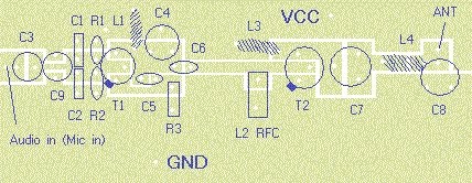
Circuit diagram:
Materially:
The resistors are 1/4W.
R1, R2 10KOhm
R3 47Ohm
C1, C2 1nF
C3 4,7uF/16V
C4, C7, C8 0~45pF trimmer
C5, C6 10pF
C9 100nF
L1 4 turns, 7mm diameter *
L3 3 turns, 7mm diameter *
L4 5 turns, 7mm diameter *
L2 RFC (resistance 1MOhm with wrapped around her inductor of enough
coils from fine isolated wire. Scratch of utmost inductor and you stick
in utmost the resistance making thus a parallel L-r circuit.)
T1, T2 2N2219
ANT Simple dipole l/2.
MIC IN Microphone dynamic or other type. (It can also connected to a cassette player unit)
* The inductors is air from wire of coaxial 75W or other 1mm roughly.
PCB:
Before you print it out with microsoft paints, set the screen resolution to 1280 by 1024 in order to get the correct scale
Before you print it out with microsoft paints, set the screen resolution to 1280 by 1024 in order to get the correct scale

Regulations:
With the C4 we regulate the frequency.
With their C7, C8 we adapt the resistance of aerial (practically to them
we regulate so that it is heard our voice in the radio as long as you
become cleaner).
With the C4 we regulate the frequency.
With their C7, C8 we adapt the resistance of aerial (practically to them
we regulate so that it is heard our voice in the radio as long as you
become cleaner).
Notes:
The T2 wants refrigerator.
The T2 wants refrigerator.
Subscribe to:
Post Comments (Atom)
No comments:
Post a Comment
Note: Only a member of this blog may post a comment.